Telcordia GR Standards are widely used in the global telecommunications industry due to their universality and practicality. There are specific categories designed for fiber optic connectors, such as Telcordia GR-326 for single-mode fiber optic connectors, Telcordia GR-1435 for multimode fiber optic connectors, Telcordia GR-1081 for fiber optic quick connectors, and Telcordia GR-2923 for fiber optic connectors cleaning products. Among these, Telcordia GR-326 for single-mode fiber optic connectors and patch cords is the most commonly used. This article will provide a comprehensive, detailed, and easy-to-understand explanation of Telcordia GR-326 standards.
GR-326-CORE was initially created by Bellcore (Bell Communications Research, Inc.). In 1999, Bellcore was officially renamed Telcordia Technologies, and in 2012, Telcordia was acquired by Ericsson. During this period, Telcordia GR-326 ("Generic Requirements for Single-Mode Optical Connectors and Jumper Assemblies") was continuously revised and improved.
The following basic information is provided for a brief introduction to Telcordia GR-326 standards:
Definition: Considered the most complete and stringent standard for single-mode fiber optic connectors. The Telcordia GR-326 standard document explains Telcordia's general technical requirements for connectors used to connect single-mode optical fibers and jumper assemblies made using such connectors.
Scope: Specifically designed for single-mode fiber optic quick connectors and jumper assemblies.
Target audience: Users or buyers of single-mode fiber optic connectors and jumper assemblies, as well as manufacturers and suppliers.
Categories: General requirements; Performance requirements; Service life testing; Extended service life testing; and Reliability assurance procedures.
GR-362 testing standards cover two types: service life testing and extended service life testing.
The former aims to simulate problems that connectors may encounter during their service life and is divided into two parts: environmental testing and mechanical testing. The latter exposes the connector to various environments, including additional environmental testing and exposure testing.
Service life testing
Environmental testing ensures that the cable assembly can withstand exposure to a temperature range of 85°C or up to 125°C during its service life and accelerates the aging effects of the jumper assembly, including six parts:
Thermal aging test
Content: Simulates and accelerates everything that may happen during product transportation and storage.
Requirement: Place the connector continuously at 85°C and uncontrolled humidity for 7 days.
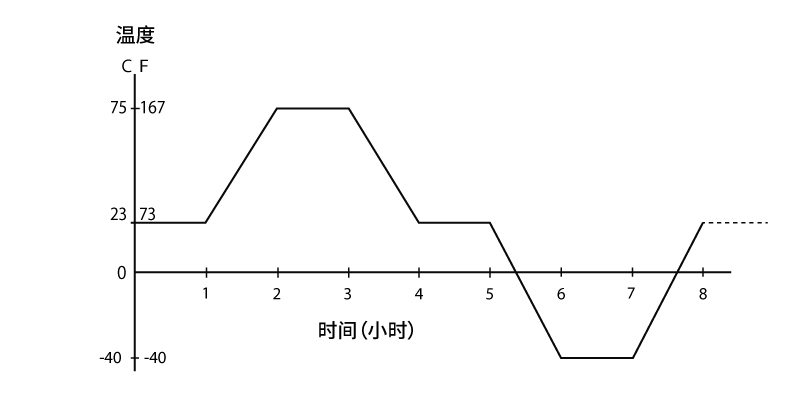
Thermal cycling test
Content: Fluctuates the temperature within a wide range - extremely hot and cold, applies heavy pressure and bacteria to the sample to check its compliance.
Requirement: Lower the environmental temperature of the connector by 115°C (from 75°C to -40°C) within three hours.

Humidity aging test
Content: Introduce moisture into the connector and determine its effects on the sample.
Requirements: Expose the connector to an environment of 95% relative humidity (RH) and maintain it at a high temperature of 75°C for 168 hours (7 days).
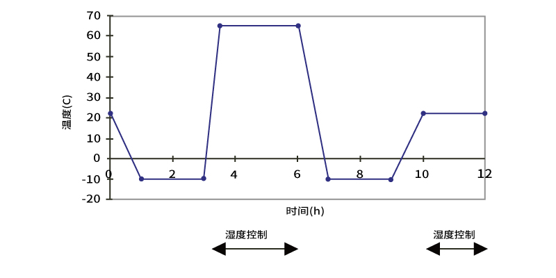
Humidity/condensation cycling test
Content: Check the effects of water on the connector when moisture undergoes rapid changes. If water molecules inside the connector components freeze or evaporate, the "gap" problem in the physical contact between the connectors in the adapter may be exposed.
Requirements: Temperature cycling from -10°C to +65°C, 90%-100% RH, for a total of 14 cycles over 168 hours (7 days).

Drying step test
Content: Remove any residual moisture from the previous humidity/condensation cycle test before the final stage of environmental testing.
Requirement: Dry for 24 hours (1 day) at 75°C before conducting the condensation heat cycle.
Post-condensation heat cycle test
Content: Similar to the previous heat cycle test. Changes that may occur in the connector during the humidity/condensation cycle are often revealed after the condensation is removed, which may affect the connector's loss and/or reflectivity.
Requirement: Conducted after the drying step.
After the aging test, mechanical tests are required, including the following test items:
Vibration test
Content: Install connector components individually or in batches in a "vibrator" to check whether high-frequency vibration affects the performance of the sample.
Requirement: Conducted for two hours on three axes, with an amplitude of 1.52mm per axis, and the frequency continuously scans from 10 to 55Hz at a rate of 45Hz per minute.
Elasticity test
Content: Intended to simulate the pressure on the terminal cable and mating connector.
Requirement: Apply a load of 0.9 kgf (for small connectors, the load can be reduced to 0.6 kgf), and then rotate the test fixture arm in the following cycle: 0°, 90°, 0°, -90°, 0°, and repeat 100 cycles. Compare the pre- and post-loss and reflectivity values.
Torsion test
Content: Apply a rotational twist to the fiber and test the strength coupled with the connector. Like the bending test, the twist test will help identify weaknesses in the termination process - the adequacy of crimping.
Requirement: After installing the test sample, apply the load according to the instructions. Then rotate the winch around the fiber axis x times and reverse the direction to rotate y times, then reverse the direction again and rotate y times. After repeating the load application procedure nine times, measure the values of loss and reflectivity. The table below shows the numerical values for the fiber connector torsion test.
| Media Type I | Media Type II | Media Type III | |
load | 1.35 kgf (3.0 lbf) | 0.5 kgf (1.1 lbf required) 0.75 kgf (1.65 lbf objective) | t 0.5kgf (1.1 lbf) |
| X number of turns | 2.5 | 1.5 | 1.5 |
| Y number of turns | 5 | 3 | 3 |
Proof test
Content: Ensure the strength of the connector latch and crimping during termination.
Requirement: Obtain loss and reflection measurements through straight pull and 90° pull tests.
TWAL (Tensile with applied load)
Content: Apply pressure to the sample by loading different weights at multiple angles. The range of weights used depends on the type and shape of the cordage.
Requirement: The tensile load value of the fiber optic connector under load transmission is shown in the table below:
Tensile load under load transmission | |||
|---|---|---|---|
Media Type I | |||
Load | 0° | 90° | 135° |
0.25 kgf (0.55 lbf) | X | X | X |
0.7 kgf (1.54 lbf) | X | X | |
1.5 kgf (3.3 lbf) | X | X | |
2.0 kgf (4.4 lbf) | X | X | |
Media Type II | |||
Load | 0° | 90° | 135° |
0.25 kgf (0.55 lbf) | X | X | X |
0.7 kgf (1.54 lbf) | X | X | |
Media Type III | |||
Load | 0° | 90° | 135° |
0.25 kgf (0.55 lbf) | X | X | |
0.5 kgf (1.1 lbf) | X | X | |
Impact testing
Content: Used to verify that the connector is not damaged when dropped.
Requirement: Install coal slag blocks at the bottom of the fixture, and drop the connector from a horizontal distance of about 1.5 meters, repeating the process eight times.
Durability testing
Content: Simulate repeated use of the connector to discover any design issues or material defects, such as severe tension or other defects that may occur in any part of the locking structure due to frequent use.
Requirement: Repeat the process of inserting the connector into the adapter (200 times) at different heights (in the order of 6 feet, 4.5 feet, 3 feet, 3 feet, 4.5 feet, and 6 feet) to simulate the usage scenario of a user standing in front of the rack at the end site.
Extended life testing
Tests are not ordered, so there is no cumulative effect. Exposed tests mainly cover the following:
Dust testing
Dust has a significant impact on optical performance, and dust particles on contaminated end faces can block optical signals and cause optical loss. This test exposes the connector to dust of a specified particle size to test whether any dust particles enter the sleeve and pose a risk of contaminating the end face.
Salt spray testing
Salt spray testing aims to ensure the performance of jumper components in a free-breathing shell near the ocean, including long-term exposure of the connector to high concentrations of sodium chloride (NaCl). Optical testing is then performed, followed by inspection to confirm that there are no signs of material corrosion.
Air pollution testing
Air pollution testing aims to ensure the performance and material stability of the connector in outdoor applications with high concentrations of pollution. Paired and unpaired connectors will be repeatedly exposed to various gases and then subjected to optical and visual inspections. The connectors will be placed in a small room that uses various volatile gases for 20 days to simulate long-term exposure of the connectors to these elements.
Immersion/corrosion testing
There are no optical requirements, but the connectors need to be immersed in uncontaminated water for a long time. By measuring the radius of curvature before and after the test and comparing these values, it is checked whether there is any deformation of the sleeve in paired connectors, while unpaired connectors need to check for fiber dissolution, including whether the fiber core has not penetrated into the fiber coating.
Underground water immersion test
Aimed at verifying the performance of connectors in underground applications. During the test, the connector will be exposed to various chemicals and biological media, such as sewage treatment and agricultural fertilizers. These chemicals include ammonia, cleaners, chlorine, and fuels.
 Three Features of ABS Cassette PLC Splitter
22 Jun 2022
PLC splitter is a PLC planar waveguide type optical splitter. PLC splitter is one of the most important passive components in optical fiber links.Ⅰ. How is the PLC splitter made?A PLC splitter is a q...
 Call us on:
  Email Us:
  8 Jinxiu Middle Road,