It is relatively easy to budget for link loss. First, we need to find the budget for each transmission speed allowed. Using this method, calculate the expected total link loss from the length of the optical fiber link, and add up all the interconnect losses. Note that fusion splicing also needs to be included, although it is not common in data centers.
Link Loss | Description | TIA-568 Max. Loss |
| Cable Attenuation | OM4, 850nm | 3.0 dB/km |
Connector | LC | 0.5 dB |
| MPO | 0.75 dB | |
Splicing | Fusion Splicing | 0.1 dB |
Following the data in the table for link loss budgeting will provide a fairly accurate estimation. However, there are other loss-related factors to consider in achieving the required data transfer speed in real-world scenarios.
Optoelectronic devices with excellent reliability and optical performance
Reasonable installation, such as controlling the bend radius of optical cables
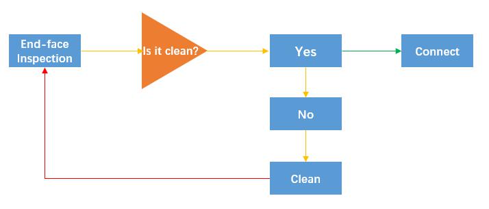
Performing fiber end-face inspection and necessary cleaning before installation
Reserving a certain loss redundancy as a buffer in loss planning
Active devices such as high-performance optical modules
It should be noted that the loss budget limit of SAN/InfiniBand devices largely depends on the sensitivity of the optical module.
Over time, aging or obsolescence of devices such as lasers and optical modules is a factor that many people overlook. Therefore, it is necessary to ensure sufficient budget redundancy in your loss budgeting, and designing it to a maximum standard link budget of 70% will be necessary. In addition, the performance of fiber optic connectors and joints terminated by fusion splicing in the infrastructure may also deteriorate. Some fiber optic connectors installed on site may also match liquid degradation and cause more loss.
With current technological means, even if all aspects of the operation are in place, connectors may still become dirty or contaminated. Fiber optic cables are thinner than hair and it is not easy to avoid contamination. Even if the cleaning is done well, the static electricity on the connector plug may attract some small particles and dust to adhere to the fiber end-face, especially in data centers with extremely low humidity.

(Figure 1: Fiber end-face cleaning)
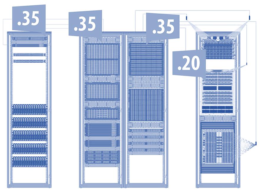
Taking into account all factors that cause or eliminate loss will ultimately enable you to build a fiber structured cabling system according to the TIA-942 standard and meet the loss budget requirements for 400G transmission. For example, see Figure 2 below. Considering all factors that cause and eliminate loss according to the TIA-942 standard will enable you to meet the loss requirements necessary for 400Gbps transmission.

(Figure 2: In this example, the total attenuation loss of the seven interconnected nodes is only 1.25 dB.)
 Selection and Detection of Fiber Optic Patch Cord
06 Dec 2021
Fiber optic cable patch cord is widely used in communication rooms, home optical fiber, local area networks, optical fiber sensors, optical fiber communication systems, optical fiber connections, tran...
 Call us on:
  Email Us:
  8 Jinxiu Middle Road,